Abstract:To identify the suitable test conditions for evaluating the compatibility between lubricating oil and polyimide enameled wire, a series of compatibility tests were conducted under varying water content levels and different cycle counts. The tests employed the cold and heat cycle impact method as specified in T/CEEIA 415—2019 "Insulation System of Driving Motor of New Energy Vehicles - Technical Requirements." The enameled wire’s appearance, breakdown voltage, and PDIV were assessed post-test, allowing for the determination of the impact of water and cycling on the compatibility test outcomes.
Key Words: motor enameled wire; polyimide; lubricating oil; water content.
Introduction
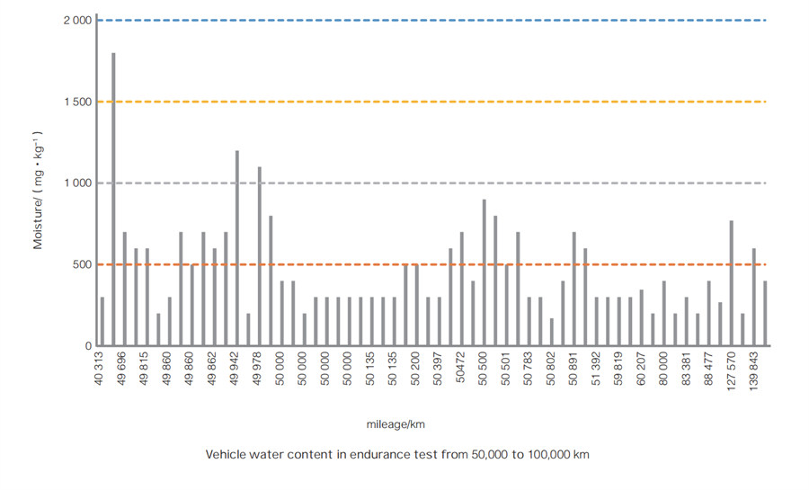
In recent years, the rapid development of the new energy vehicle industry has led to continuous improvements in motor performance and efficiency to meet the operational demands of electric vehicles. High-power-density motors have become increasingly common, and oil cooling technology is being rapidly adopted in electric vehicles due to its superior heat dissipation efficiency. The working temperature of new energy vehicle transmissions typically ranges from 80°C to 130°C, with the surface temperature of the motor potentially exceeding 180°C, far higher than the normal operating temperature of transmission oil. These high temperatures place greater demands on the compatibility between the motor’s polymer insulation materials and the transmission oil, particularly regarding high-temperature thermal stability, thermal oxidation, and hydrolysis, with hydrolysis being a significant industry concern.
This study used polyimide-type flat enameled wire as the insulation layer. Currently, the industry lacks a unified testing method for assessing the compatibility of drive motor oils with enameled wire under water contamination. Therefore, the testing method was based on the oil resistance evaluation method for insulation components in T/CEEIA 415—2019.

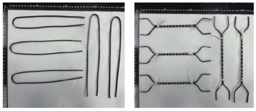
Figure1
|
Project |
Typical value |
Test method |
|
Density(15 ℃)/(kg ·m-3 ) |
0.821 |
ASTM D4052 |
|
Knematic viscosity(100 ℃)/(mm2 ·s-1 ) |
4.11 |
ASTM D445 |
|
Kinematic viscosity(40 ℃)/(mm2 ·s-1 ) |
18.06 |
ASTM D445 |
|
Brookfield viscosity(-40 ℃)/(mPa ·s) |
3 623 |
ASTM D2983 |
|
Flash point (opening)/℃ |
216 |
ASTM D92 |
|
Moisture/(mg ·kg-3 ) |
264 |
ASTM D6304 |
|
Pour point/℃ |
-45 |
ASTM D97 |
|
Foam properties |
|
ASTM D892 |
|
ProgramI/(mL/mL) |
10/0 |
|
|
ProgramII/(mL/mL) |
20/0 |
|
|
ProgramIII/(mL/mL) |
10/0 |
|
|
Copper corrosion(150 ℃,3 h)/CLASS |
1b |
ASTM D130 |
Table1:Transmission oil physical and chemical data
|
Project |
Model |
Factory |
|
Rapid temperature change box |
SE-1000-17-17 |
ELitech |
|
Small environmental warehouse |
KWGDS61 |
THERMOTRON |
|
Coulomb kf titrator |
C30SD |
Chongqing Galaxy Testing Instrument Co., Ltd. |
|
Thermohygrometer |
BT-2 |
METTLER TOLEDO |
Table2:Test instrument information
1.1 Experimental Materials, Oils, and Instruments
The enameled flat wires used in the tests were produced by Taiyi Copper Industry and formed into U-shaped and back-to-back shapes in Figure 1. The transmission oil used in the tests has been employed in oil-cooled motors for many years, with typical physical and chemical data provided in Table 1. The testing instruments included a rapid temperature change chamber, a small environmental chamber, and others in Table2.
1.2 Test Procedure
1.2.1 Test Preparation
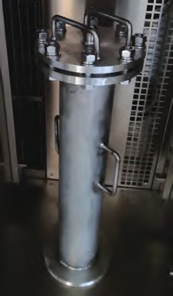
Five U-shaped and five back-to-back shaped enameled wires were placed in sealed tubes(Figure 2)containing a mixture of transmission oil and deionized water, with the water content levels set at 0%, 0.2%, and 0.5%. The wires were fully submerged in the oil medium, and the tubes were completely sealed throughout the test.
1.2.2 Test Cycle
Before the test, the sealed tube samples were placed in a high-temperature chamber at a lab temperature of 25°C ±5°C. The chamber was then heated to 155°C ±2°C and maintained for 40 hours, including the heating time. Afterward, the sealed tubes were transferred to a low-temperature chamber at -45°C ±2°C for 8 hours. This constituted one cycle. The test was conducted for 8 and 12 cycles. After the cycles were completed, the samples were removed and allowed to return to room temperature before evaluating the appearance, breakdown voltage, and PDIV.

Figure2

1.2.3 Test Matrix
The test matrix and procedures followed are detailed
Results and Discussion
2.1 Test Results
After removing the enameled wires from the sealed tubes, the surface oil was wiped off, and the coating thickness, breakdown voltage, PDIV, and post-test water content in the
transmission oil were measured according to the methods outlined(Table4).
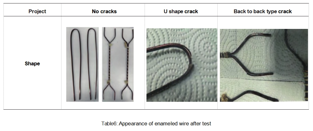
The appearance in Table5, breakdown voltage, and PDIV results for the enameled wires tested under different water content and cycle conditions, as well as the water content in the transmission oil after the test, are shown in Table5 and Table6.
|
Project |
Appearance |
Paint film thickness/mm |
Average breakdown voltage/kV |
Average /V |
Water content in gearbox oil after test/(mg ·kg-1) |
|
|
New line before trial |
Smooth without scratches |
Width:0.262;thick:0.262 |
>11 .81 |
2 043 |
— |
|
|
0%water |
U shape |
5 no cracks |
Width:0.265;thick:0.268 |
>12.74 |
— |
25 |
|
8cycle Back to back type |
5 no cracks |
Width:0.265;thick:0.268 |
— |
2 260 |
25 |
|
|
0%water |
U shape |
5 no cracks |
Width:0.265;thick:0.269 |
>12.76 |
— |
36 |
|
12cycle Back to back type |
5 no cracks |
Width:0.265;thick:0.269 |
— |
1 976 |
36 |
|
|
0.2%water |
U shape |
4 no cracks |
Width:0.265;thick:0.269 |
>12.61 |
— |
1 019 |
|
8cycle Back to back type |
3 no cracks |
Width:0.265;thick:0.269 |
— |
1 885 |
1 019 |
|
|
0.2%water |
U shape |
0 no cracks |
Width:0.270;thick:0.265 |
— |
— |
1 032 |
|
12cycle Back to back type |
1 no cracks |
Width:0.270;thick:0.265 |
— |
1 846 |
1 032 |
|
|
0.5%water |
U shape |
0 no cracks |
Width:0.269;thick:0.270 |
— |
— |
3 346 |
|
8cycle Back to back type |
0 no cracks |
Width:0.269;thick:0.270 |
— |
— |
3 346 |
|
|
0.5%water |
U shape |
0 no cracks |
Width:0.270;thick:0.271 |
— |
— |
3 026 |
|
12cycle Back to back type |
0 no cracks |
Width:0.270;thick:0.271 |
— |
— |
3 026 |
|
Table5:Appearance, breakdown voltage PDIV of enameled wire under different water contents and different cycles

Conclusion
1. As the water content in the transmission oil of new energy vehicles increases over time, the hydrolysis rate of the polyimide insulation coating on the enameled wire accelerates.
2. After high and low-temperature tests, when the water content in the transmission oil reaches 0.5%, the polyimide insulation coating on the enameled wire rapidly hydrolyzes, with all samples cracking after 8 cycles.
3. In compatibility tests between enameled wire insulation coatings and transmission oil, it is recommended to add 0.2% deionized water to the transmission oil and conduct 8 cycles according to the oil resistance evaluation method in T/CEEIA 415—2019.